If you’re working on a project that calls for a DC motor—whether it’s a robotics arm, a conveyor belt, a medical pump, or a small electric vehicle—one of the most common, and often trickiest, calls you’ll have to make is choosing the right shaft diameter. I’m a DC motor supplier, and for years, I’ve talked to engineers, hobbyists, and even product managers who either size this part wrong the first time, or switch motors halfway through a build because the shaft doesn’t work. It’s a fixable problem, and it doesn’t have to require a degree in mechanical engineering to get right. Let’s break this down step by step, from the basic physics you need to know to the small, easy-to-miss details that can make or break your design. DC Motor
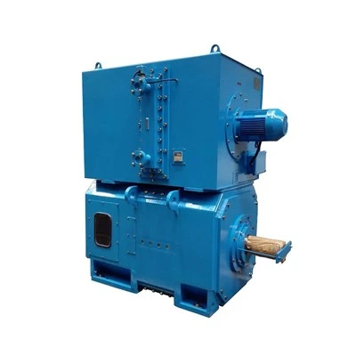
First, let’s start with why shaft diameter matters so much. The shaft is the direct link between the motor’s internal components—the armature, bearings, and magnets—and whatever you’re powering: a gearbox, a pulley, a wheel, or a propeller. If the shaft is too thin, it will bend under load, a problem called “shaft deflection.” That bend doesn’t just throw your load off alignment; it can wear out the motor’s bearings faster, cause vibration, and even break the shaft entirely over time. If it’s too thick, you’ll waste space, add unnecessary weight, and your motor’s mount, gears, or couplings won’t fit without custom modifications, which cost time and money. For a DC motor, the shaft isn’t just a rod—it’s a load-bearing part that ties the motor’s electrical output to its mechanical use, so getting this number right sets the foundation for everything that comes after.
Before you even look at a motor’s specs, you need to calculate the torque your shaft will have to handle. Torque is the twisting force that makes your load move, and it’s the single biggest driver of shaft diameter. The formula here is simpler than it sounds: Torque (T) equals Force (F) multiplied by Radius (r) of the load you’re turning. For example, if you’re powering a pulley that’s 5 centimeters in diameter (so radius is 2.5 cm, or 0.025 meters) and your conveyor belt exerts 100 Newtons of force on the pulley, your torque is 100 N * 0.025 m = 2.5 N·m. That number tells you how hard your shaft will have to twist.
Once you have your required torque, you use that to find the minimum safe shaft diameter using the bending stress formula, a basic engineering rule of thumb. Bending stress (σ) is how much force is pulling the shaft apart along its length, and for most steel shafts (the material we use for standard DC motor shafts, since it balances strength and cost), the maximum safe stress for continuous use is around 55 megapascals (MPa) for low-speed applications, or 45 MPa for high-speed, high-cycle uses (like a robotics arm that moves hundreds of times a day). The formula to find minimum shaft diameter (d) in meters is d = cube root of (32Fr / (π*σ)). Wait, let’s make that tangible for non-engineers: if your torque is 2.5 N·m, and you’re using a standard low-stress shaft for a conveyor, your minimum diameter is around 8 millimeters. If torque jumps to 5 N·m, that jumps to around 10 mm. This isn’t just guesswork—this calculation is backed by decades of mechanical design standards, so it’s hard to mess up if you plug in the right numbers.
But wait—torque isn’t the only force acting on the shaft. You also have to account for “overload torque.” That’s the extra force that hits your shaft when you start the motor, or when your load jams, or when you’re moving a heavy object up an incline. A lot of people make the mistake of sizing their shaft only for the continuous torque their motor needs to run, not the brief spikes that happen during normal use. For most consumer and industrial applications, plan for overload torque that’s 1.5 to 2 times your continuous torque. That means if your continuous torque is 2.5 N·m, you size your shaft for 3.75 to 5 N·m, which pushes that minimum diameter up to 9 or 10 mm, not 8. Skip this step, and your shaft will bend the first time your conveyor belt hits a small bump, or your robotics arm lifts a load that’s a little heavier than you planned.
Next, don’t overlook fit—this is where a lot of hobbyists and small-project teams go wrong. Shaft diameter isn’t just about strength; it has to fit the parts you’re connecting to it: couplings, gears, pulleys, wheels, and the motor’s own bearings. For example, if you’re using a standard 6-mm set screw coupling, you can’t just order a 10-mm shaft and grind it down to fit—that will weaken the shaft to the point where it breaks under load. And don’t assume all 8-mm shafts are the same: some manufacturers build shafts with a “keyway” (a small slot to lock a gear in place, so it doesn’t slip) while others are smooth. If your gear has a keyway, you’ll need to adjust your diameter calculation, because the keyway cuts into the shaft and reduces its strength by around 25%. I’ve had a customer come to me last year who built a small farm gate opener, ordered a motor with an 8-mm smooth shaft, and tried to press a 8-mm gear with a keyway onto it—no one makes that part, so he had to rework his entire gate mechanism at his own cost. That’s a avoidable mistake.
Another fit detail: tolerances. Shafts aren’t perfect; they have a small variance in their actual diameter, called a tolerance. The most common tolerance for DC motor shafts is h9, which means the shaft is 0 to 0.036 mm smaller than the nominal diameter (so an 8-mm h9 shaft can be anywhere from 7.964 to 8.000 mm). If you’re using a press fit to connect a gear or pulley to the shaft, you need to check that the bore of your part matches the shaft’s tolerance. For example, a 8-mm bore part with a H7 tolerance is 8.000 to 8.015 mm, which will fit perfectly on an h9 shaft with a small press fit. If you mix up tolerances, your part will be too loose and slip, or too tight and you’ll damage both the shaft and the part when you press it on. I always recommend asking your motor supplier for the shaft’s tolerance rating upfront—don’t just rely on the nominal size listed on a spec sheet.
Material also plays a small but important role. Most DC motor shafts are made of carbon steel, which is strong, affordable, and resistant to wear. But if your application is in a harsh environment—like a marine robot, a outdoor conveyor that’s exposed to rain, or a medical device that needs to be sterilized regularly—you’ll want a stainless steel shaft instead. Stainless steel is about 30% less strong than carbon steel, so you’ll need to increase your shaft diameter by 10 to 15% to keep the same strength. For example, a carbon steel shaft for 5 N·m torque is 10 mm, so a stainless steel shaft would need to be 11 or 12 mm. It’s a small adjustment, but it’s what keeps the motor from rusting or breaking down after a few months of use.
Now, let’s talk about size for different motor types, because that’s a shortcut you can use if you don’t want to do the full calculation. For small, low-torque applications—like a 12-V DC motor for a desk fan, a small toy robot, or a portable water pump—you’ll typically find shaft diameters between 3 mm and 6 mm. These motors have torque under 1 N·m, so their shafts are thin enough to save space and weight, but strong enough for their load. For medium-torque applications, like a 24-V motor for a conveyor belt up to 50 kg, a robotics arm joint, or a scooter hub motor, shaft diameters usually run from 8 mm to 12 mm. For high-torque applications—like a motor for a forklift, a heavy-duty conveyor, or a industrial pump with torque over 10 N·m—shaft diameters are 14 mm and up, sometimes even 20 mm for very large motors. That’s not a hard rule, but it’s a good starting point to avoid wasting time on calculations for small projects.
Let’s also cover the most common mistakes I see, as a supplier who’s helped hundreds of customers fix bad shaft diameter choices. The first is choosing a shaft based on the motor’s frame size alone. Frame size is the diameter of the motor’s housing, not the shaft, and it doesn’t always correlate. A 42-mm frame motor (a popular size for robotics) can have a shaft diameter of 8 mm or 10 mm, depending on the motor’s torque rating. If you just pick a 42-mm frame motor without checking the shaft diameter, you might end up with a shaft that’s too small for your load. The second mistake is ignoring shaft length. The shaft’s length (how much extends out of the motor housing) also matters for deflection. A long, thin shaft is more likely to bend than a short, thick one, even if they have the same diameter. If your shaft has to extend 50 mm to reach your pulley, you’ll want to go up one diameter from your minimum calculation to account for extra length. The third mistake is forgetting the coupling. Couplings connect the motor shaft to your load’s shaft, and they have their own minimum shaft diameter. For example, a standard flexible coupling for small motors might only fit shafts up to 6 mm, so if you need a 8-mm shaft, you’ll need a larger coupling, which might require you to adjust your motor mount.
I mentioned earlier that this is a mistake I saw last year, and it’s one that still happens weekly. A customer building a mobile food cart’s conveyor system came to me with a 100-kg load, designed for a 2.5 N·m continuous torque, and ordered a motor with an 8-mm shaft. He didn’t account for the overload torque when the cart went up a 10-degree hill, so when he tested it, the shaft bent just enough to break his gear teeth and throw off the alignment. We swapped him to a 10-mm shaft, adjusted the coupling, and he hasn’t had an issue since. That’s why taking the extra 10 minutes to check all these details saves you hours of downtime and rework later.
If you’re still not sure what shaft diameter is right for you, here’s a simple step-by-step checklist to run through before you order: First, calculate your continuous torque, then multiply by 1.5 to 2 for overload torque. Use that number with the bending stress formula to get a minimum diameter. Then, check the diameter of any gears, couplings, or pulleys you’re already using to make sure your motor’s shaft will fit. If your shaft has a keyway or extra length, add 10 to 15% to your diameter to account for strength loss. Finally, confirm the material (carbon steel for indoor use, stainless for outdoor or harsh environments) and the tolerance rating with your supplier.

At the end of the day, choosing a DC motor’s shaft diameter is all about balancing strength, fit, and space. You don’t need to overengineer it with a shaft that’s twice as thick as you need—that will add unnecessary weight and cost to your motor. But you also don’t want to skimp on strength and end up with a motor that fails when you need it most. As a DC motor supplier, I’ve worked with engineers building satellite components, hobbyists building custom go-karts, and small business owners building medical devices, and the one consistent piece of advice I give everyone is: don’t guess. Do the quick torque calculation, check your fit parts, and confirm all details with your supplier before you place your order. If you’re still working through your design, or want to double-check your shaft size, my team is ready to help you review your specs and find the right motor for your project.
Explosion Proof Motor References
Shigley, J. E., & Mischke, C. R. (1989). Mechanical Engineering Design (5th ed.). McGraw-Hill.
Bickford, J. H. (1992). An Introduction to the Design and Behavior of Bolted Joints (2nd ed.). Marcel Dekker.
American National Standards Institute. (2011). ANSI B106.1M-1985: Design of Shafting for Power Transmission.
Xian Putai Electric Motor Equipment Co., Ltd.
Xian Putai Electric Motor Equipment Co., Ltd. is one of the most professional dc motor manufacturers and suppliers in China, also supports customized service with low price. Welcome to buy advanced dc motor in stock here from our factory. If you have any enquiry about quotation, please feel free to email us.
Address: Haibo Guangchang Fengcheng Nine Road Economical & Technological Development District Xi’an City Shaanxi Province – China
E-mail: sales@putaimotor.com
WebSite: https://www.putaimotor.com/
